Scene Management
Overview
A Scene is the smallest unit for organizing and displaying digital twin models, used to carry the virtual mapping of physical entities. The core purpose of configuring a scene is to define model binding relationships, interaction logic (such as Hotkey settings), and data display (such as real-time device points and Twins Asset information), ensuring the effective implementation of virtual model and physical entity status synchronization, asset association, and spatial navigation functions.
Usage Process
Configuring a scene requires three steps:

Access Method and Prerequisites
How to access
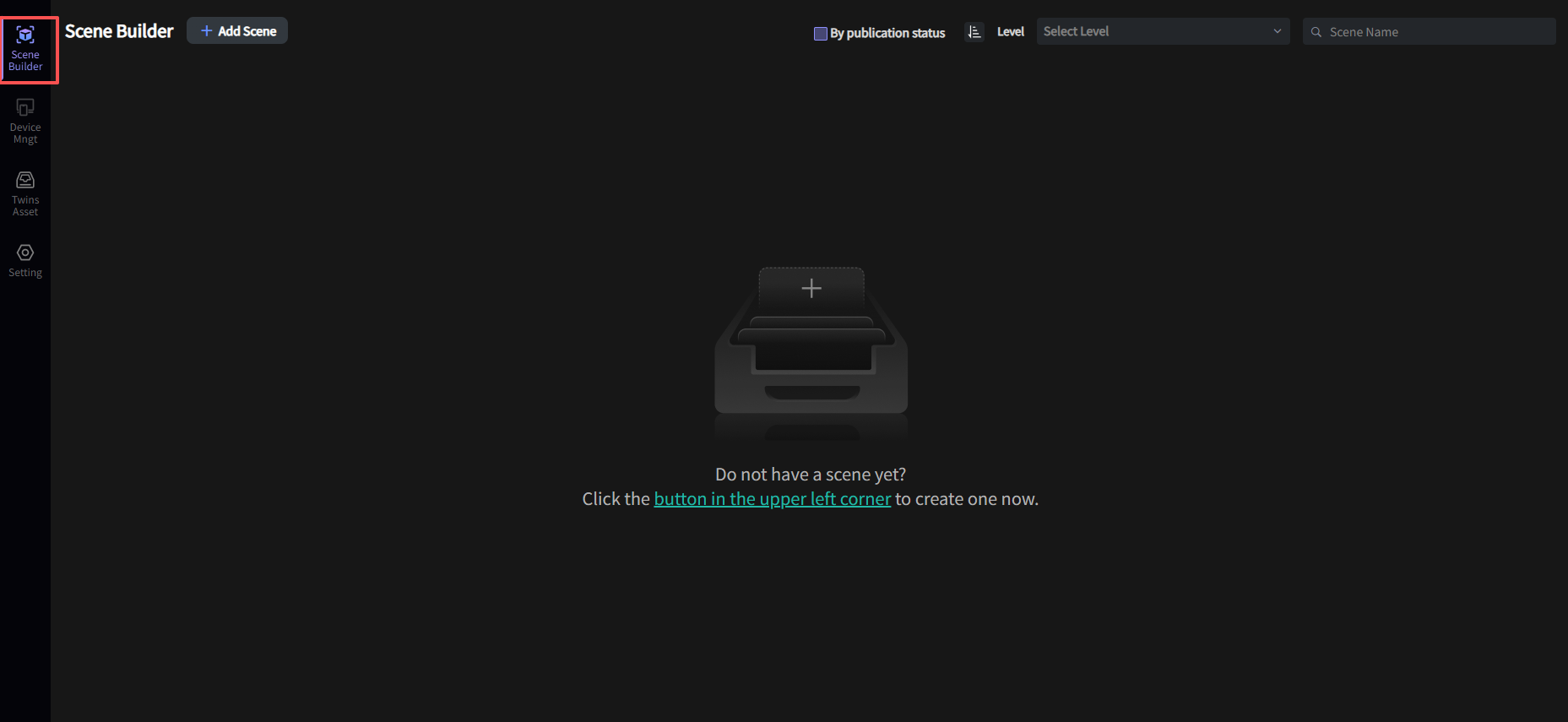
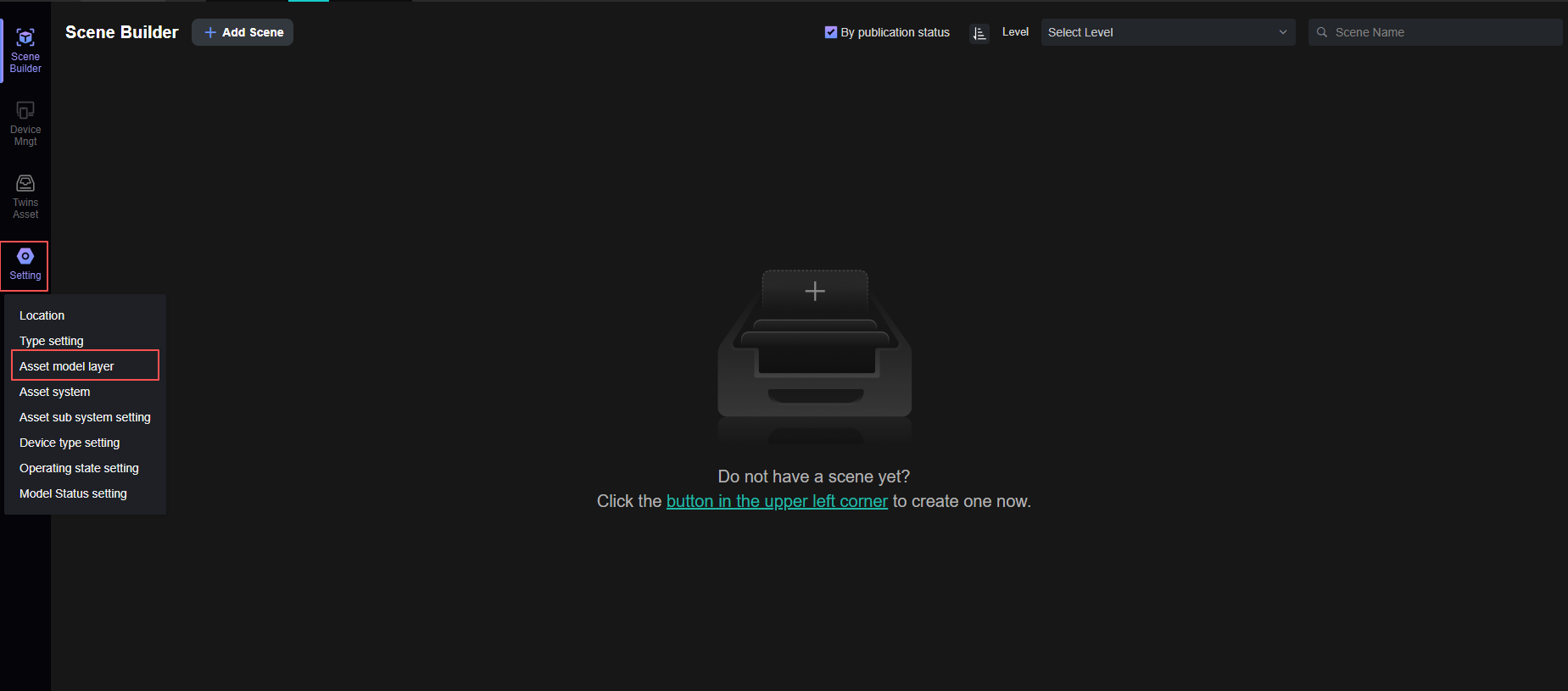
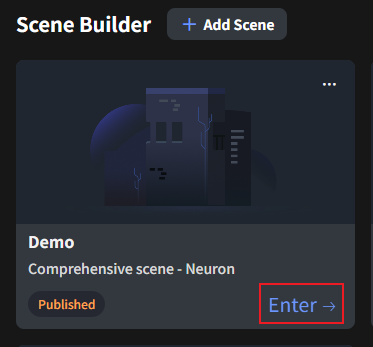
After entering the application, click "Scene Builder" in the left menu bar to view the scene panel:
Before You Start
Permission Configuration
To ensure normal use, your account needs Project Administrator permissions to add/edit/delete/publish scenes.
Prerequisite Configuration
-
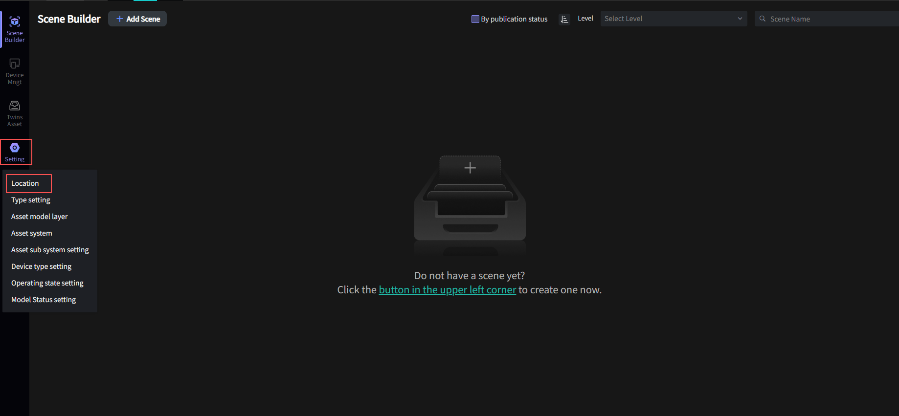
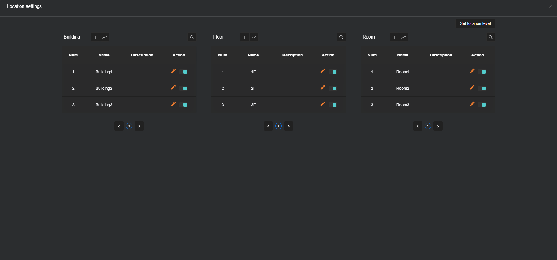
Before creating a scene, you need to configure Location information. There are two ways: one is through the left menu bar Settings -> Location configuration, as shown below; the other is detailed in Platform Location Configuration.
-
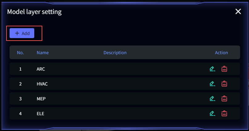
Before single-bind/bulk-bind model, you need to configure Model Layer information. Go to the left menu bar Settings -> Model Layer configuration, and click Add on the configuration page, as shown below:
Scene Panel
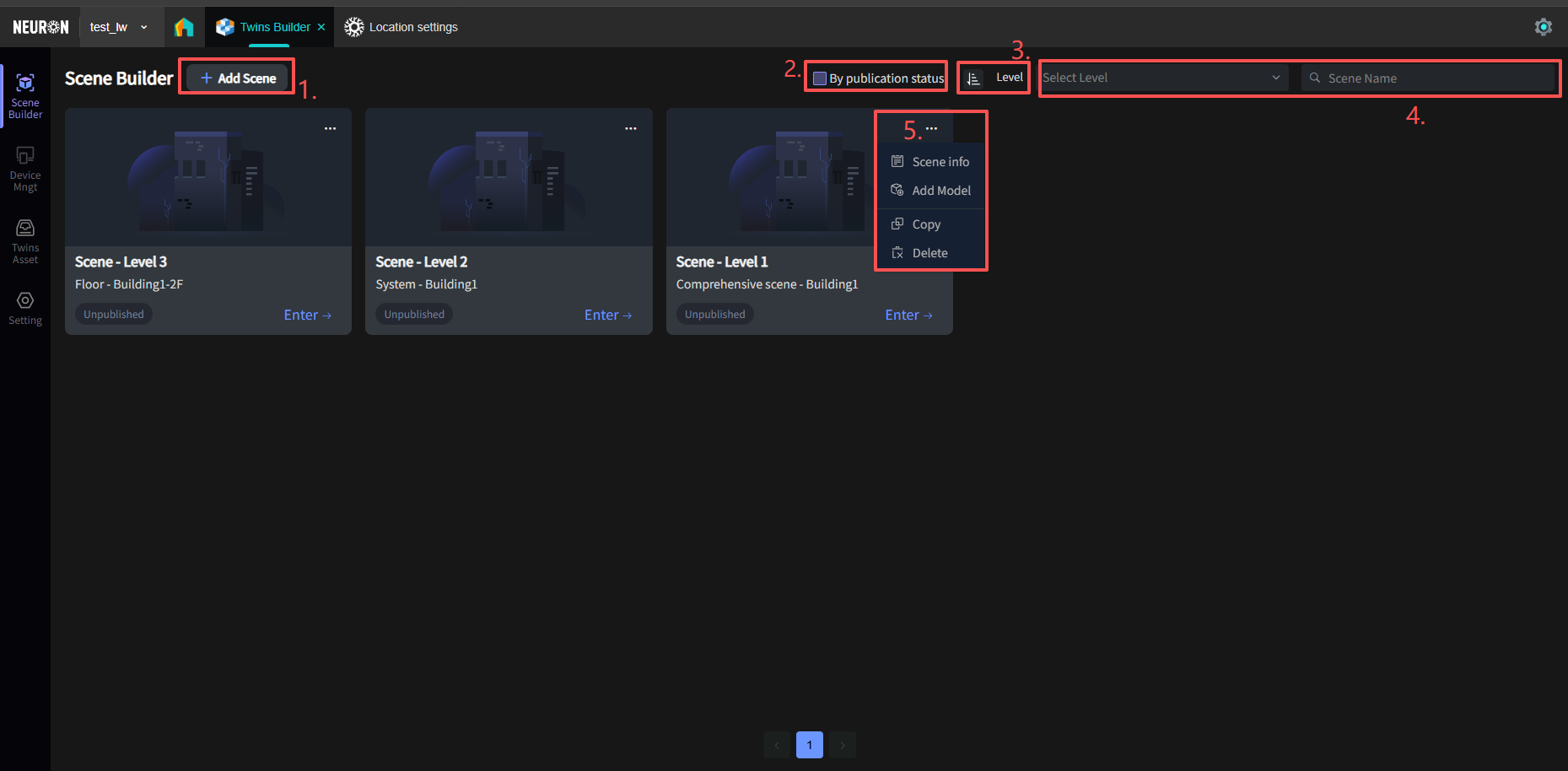
- Add a new scene;
- Filter by scene publication status (i.e., published or not);
- Adjust the position of scenes; you can prioritize important scenes;
- Search by scene level and scene name;
- Scene editing: From top to bottom: Scene Information, Add Model, Copy Scene, Delete Scene.
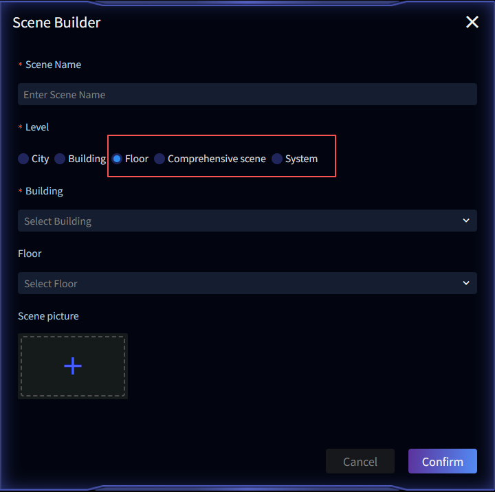
Scene Creation
Click Add Scene. Scene Name, Level, and Building are required fields.
Note: Model levels are divided into five types: City, Building, Floor, Comprehensive scene, and System: City scenes provide city-level spatial overview, Building scenes focus on single building structural views, Floor scenes enable floor-level model display, Comprehensive scene provides overall project views, System scenes target operational monitoring of specific building systems (e.g., HVAC).
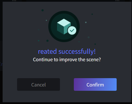
If creation is successful, a pop-up will appear asking if you want to continue improving the scene - confirm (add models immediately) or cancel (add models later).
Single Model Binding
After the Neuron technical team processes the submitted model, two types of standardized access links will be generated: a URL or a Model Key. Users must fill the corresponding model link into the appropriate configuration field according to system requirements.
Adding via Model URL Format
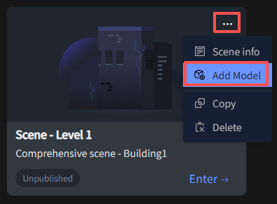
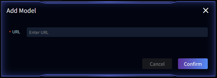
Model URL format is typically used for City or Comprehensive scene models. Find the scene needing a model in the scene list, click the top-right More -> Add Model, open the Add Model interface, and enter the Model URL in the URL field.
Adding via Model Key Format
Model Key format is typically used for System or Floor scene models. Find the scene needing a model in the scene list, click the top-right More -> Add Model, open the Add Model interface, and fill in Model Floor, Model Name & Layer, Model Key (Model Binding Type must be set to Model Key).
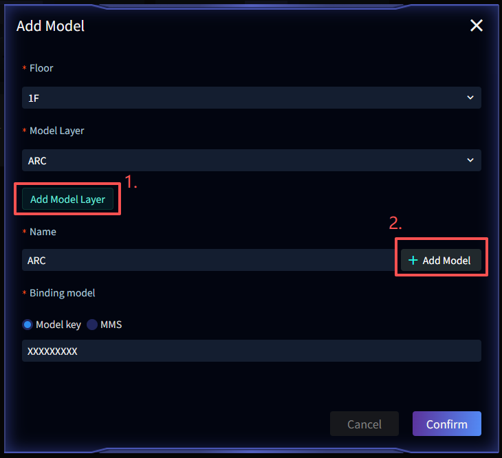
Within a single scene, multiple Model Keys can be configured (usually split based on system dimensions). Each Model Key must be associated with an independent model layer, enabling separate model display by system or layer during scene rendering.
1. Model Layer: Click the dropdown to select an existing layer. If none match, click Add Model Layer (click this button to add or refer to Pre-configuration above);
2. Add Multiple Models: To configure multiple Model Keys in a single scene, click Add Model.
Bulk Model Binding
Select the target scene in the Scene Panel, click the scene image to enter the model list, and perform the bulk import operation.
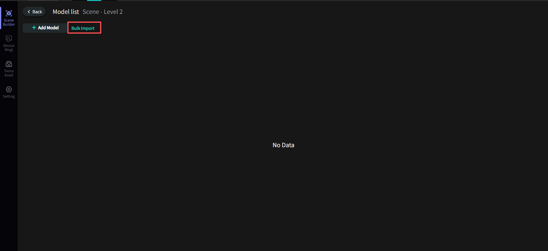
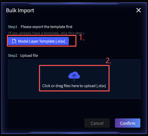
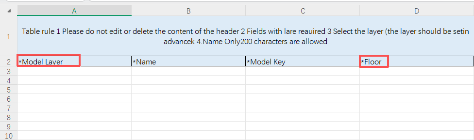
- Download the template and fill in the scene model information;
- Upload the file.
Note: Before bulk binding models, ensure the required model layers and floors have been pre-created. This is a prerequisite before export can be performed. See prerequisite-configuration for details.
Scene Interaction Configuration
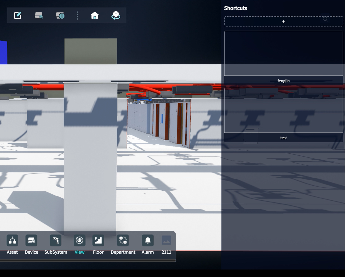
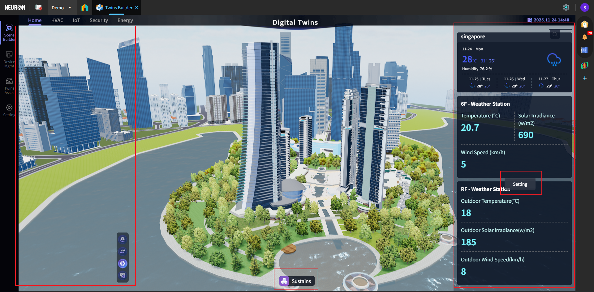
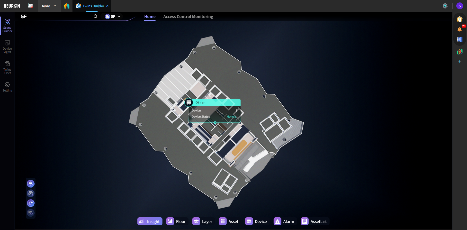
Click the 【Enter】 button on the scene list page to enter the target model.
In the scene's left, right, and bottom menu areas, right-click and select 【Setting】 to enter the settings interface:
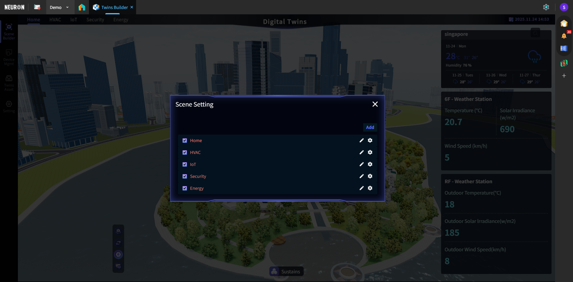
Settings Interface
Supports configuring interactive display functions within the scene and adding sub-scenes. Currently, City and Comprehensive Scene type scenes support sub-scene configuration.
Note: Each sub-scene can independently define model binding relationships, interaction logic (e.g., Hotkeys), and data display content (e.g., real-time device points and Twins Asset information), achieving synchronization and linkage between virtual models and physical entities at the status, asset, and spatial levels.
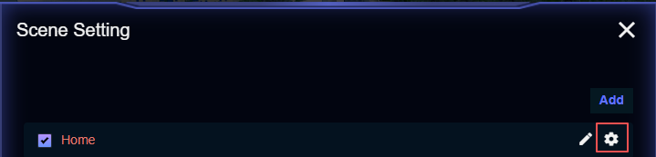
Sub-scene Settings
The list displays all sub-scenes under the current scene. The system pre-configures some sub-scenes; users can also add their own based on actual needs.
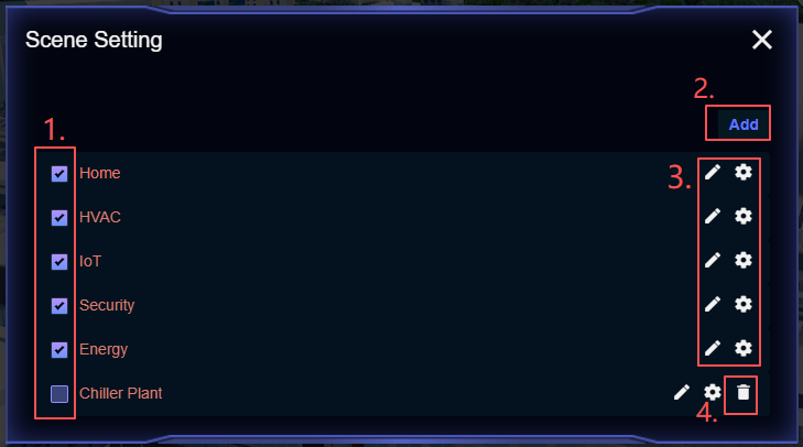
- Sub-scene Display Toggle: Check to display this sub-scene in the model. When viewing the model, users can click the corresponding sub-scene for quick navigation;
 This function is suitable for configuring independent sub-scenes by different business dimensions within a unified model scene, e.g., setting the building's energy status, parking lot, elevator operation, CCTV, etc., as separate sub-scenes. Each sub-scene can have its own dedicated Dashboard, helping users focus on specific issues and enabling independent viewing and management per scene.
 - Add Sub-scene;
- Sub-scene Edit and Configuration;
- Sub-scene Delete (only self-added scenes can be deleted).
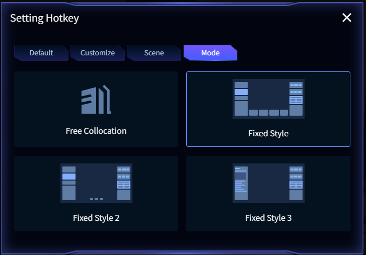
Scene Mode Settings
Supports configuring dashboard style templates for sub-scenes. Click 【Settings】 for the corresponding sub-scene, enter the 【Mode】 panel. The system currently supports four fixed styles.
Example: Displaying CCTV within the project:
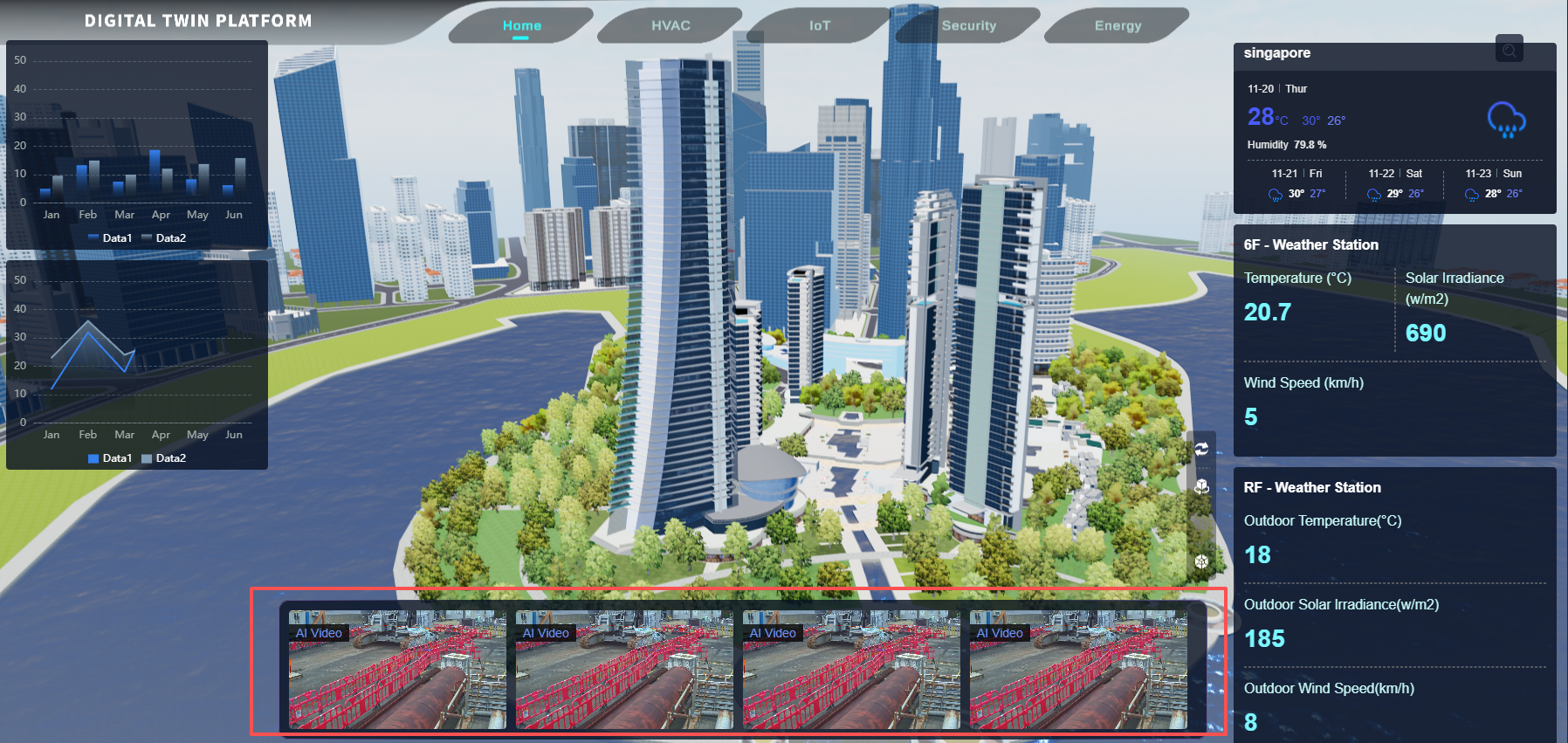
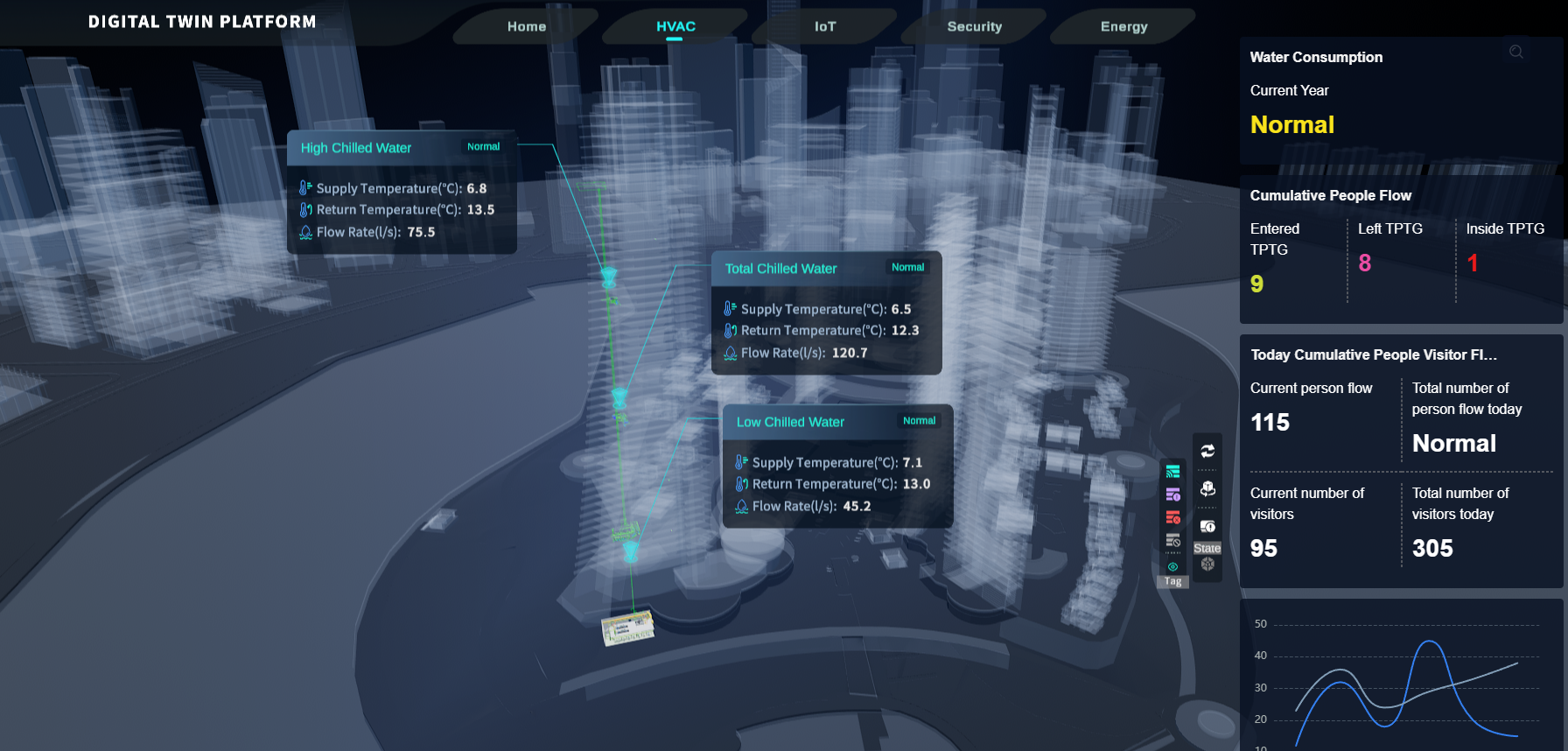
Displaying only the right-side dashboard:
Scene Default Configuration
Upon entering a scene, the system supports pre-configuring default data display rules, such as automatically displaying devices with specific statuses, keeping device tags always visible, or automatically opening specified link pop-ups when triggered.
Click 【Settings】 for the corresponding sub-scene, enter the 【Scene】 panel.
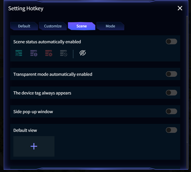
- Auto-Enable Scene Status: To display devices with specific statuses by default upon entering the scene, check the target status(es) and enable this switch (the eye icon controls the visibility of that status);
- Auto-Enable Transparent Mode: To view internal building components (e.g., HVAC systems), enable this switch to automatically activate transparent mode;
- Always Show Device Tags: To display tags for a certain device type by default upon entering the scene, configure the device type and enable this item;
- Side Pop-up: To display an external link upon entering the scene, configure the link and enable this switch;
- Default View: To change the default viewing angle when entering the model, configure this item;
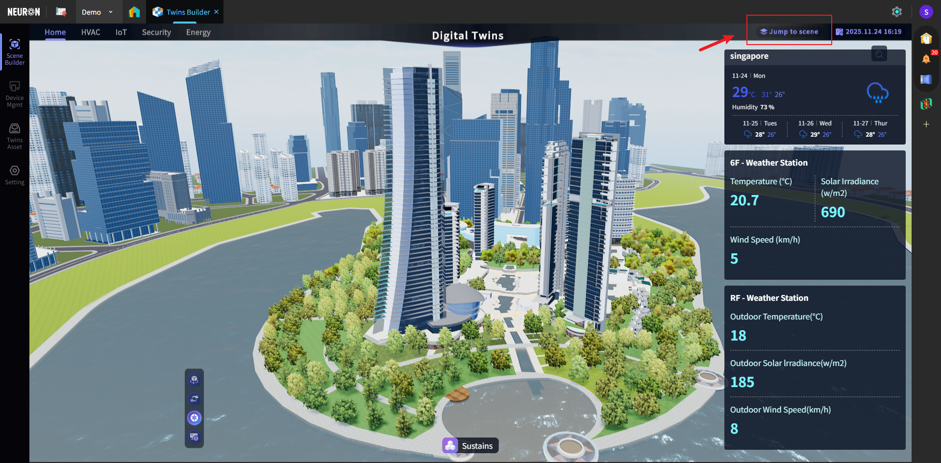
- Jump to Scene: To navigate to other model scenes, configure this item. A jump button will appear in the top-right corner of the scene after configuration;
- Device Type Tags: This option applies only to System scenes. When devices matching the configured type(s) exist in the scene, status summary tags for the device type will appear within the scene.
Hotkey Settings
Each scene supports custom Hotkeys for quickly activating preset views, functions, or information panels. Using a Floor scene as an example: Enter the scene, right-click in the left, right, or bottom menu areas, select 【Setting】, enter the 【Default】 panel:
- Edit Hotkey;
- Hotkey Display Toggle;
- Hotkey Copy.
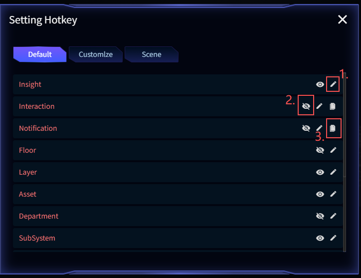
As shown, hotkeys can be associated with various elements including: Insight (data dashboards), Interaction (interactive operations), Notification (notifications), Floor (floors), Layer (layers), Asset (assets), Department (departments), and SubSystem (subsystems).
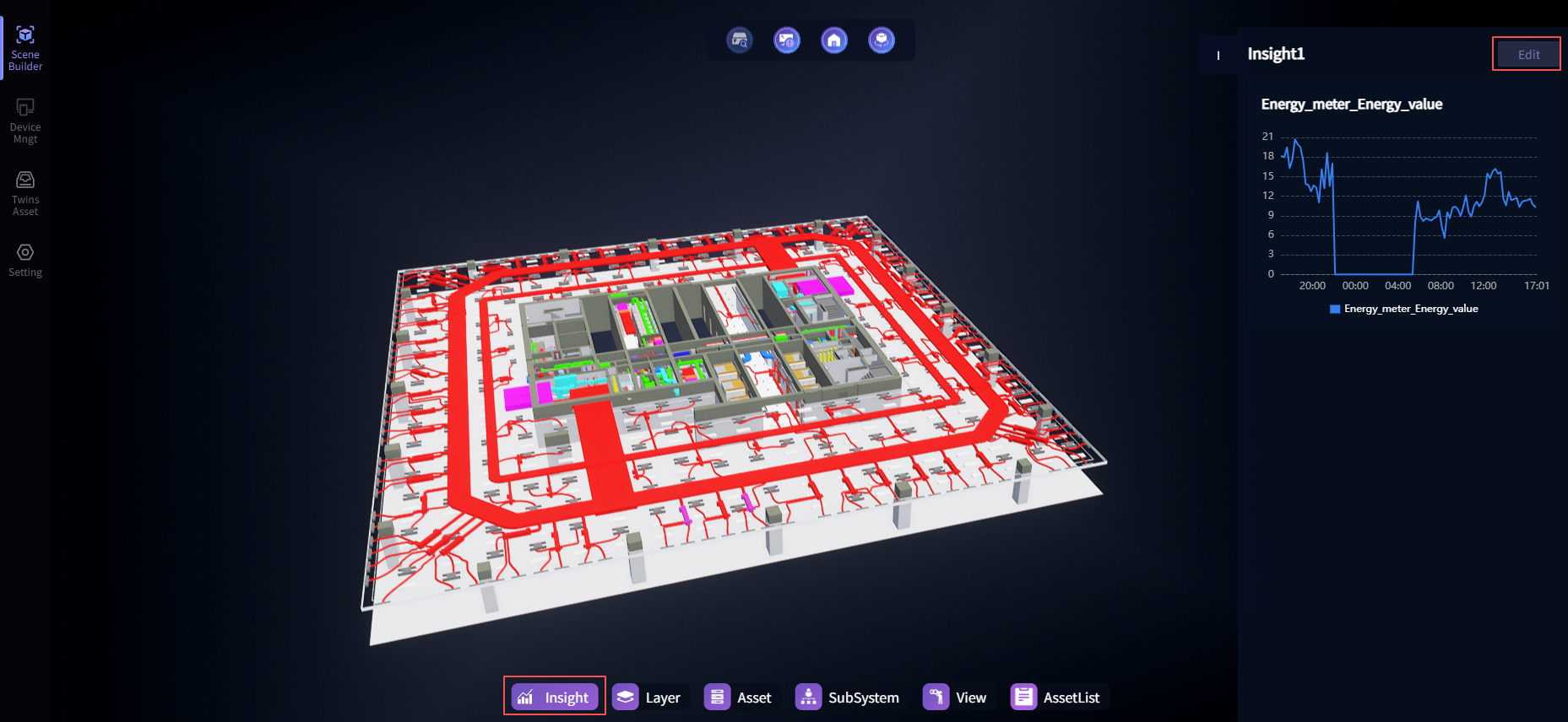
Insight (Charts/Dashboards)
After configuration, supports customizing charts on both sides of the model to achieve data visualization.
Enter the Insight item to configure the chart panel. Multiple chart panels can be configured within the same scenario, and can be switched via tabs on the drawer.
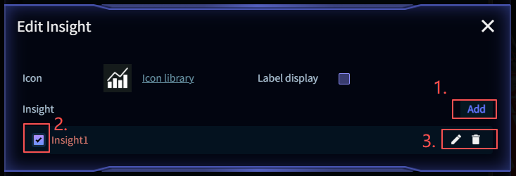
- Add chart panel
- Chart panel display toggle
- Edit name/Delete
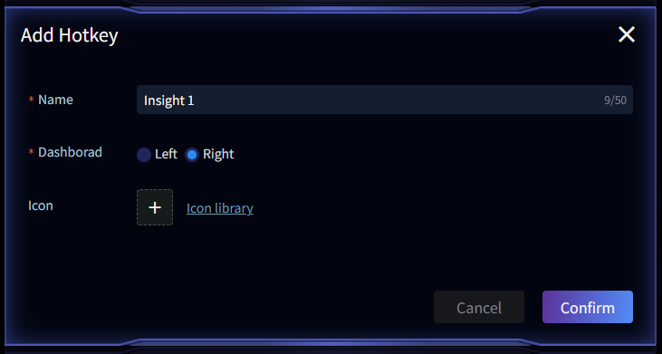
Add Chart Panel
Enter the chart panel name and placement location, then check the toggle switch after adding.
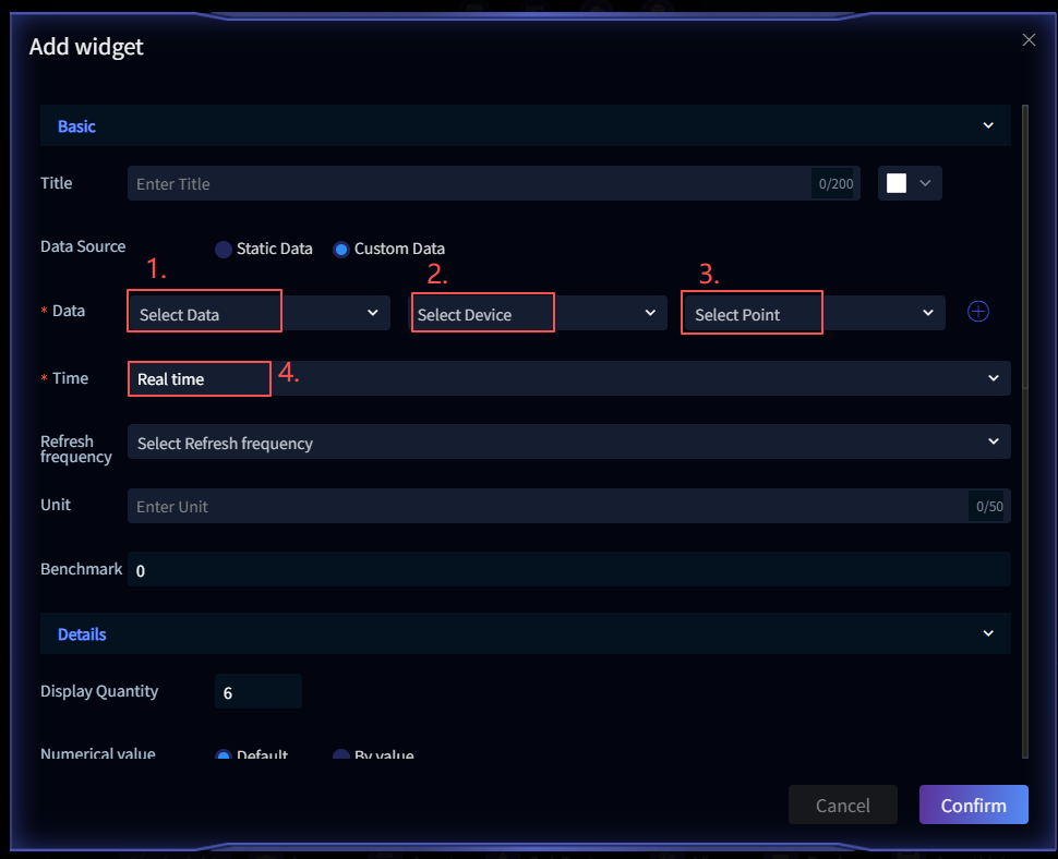
Configure Wedget
Hover the mouse over the Insight drawer -> Edit -> Select chart style.
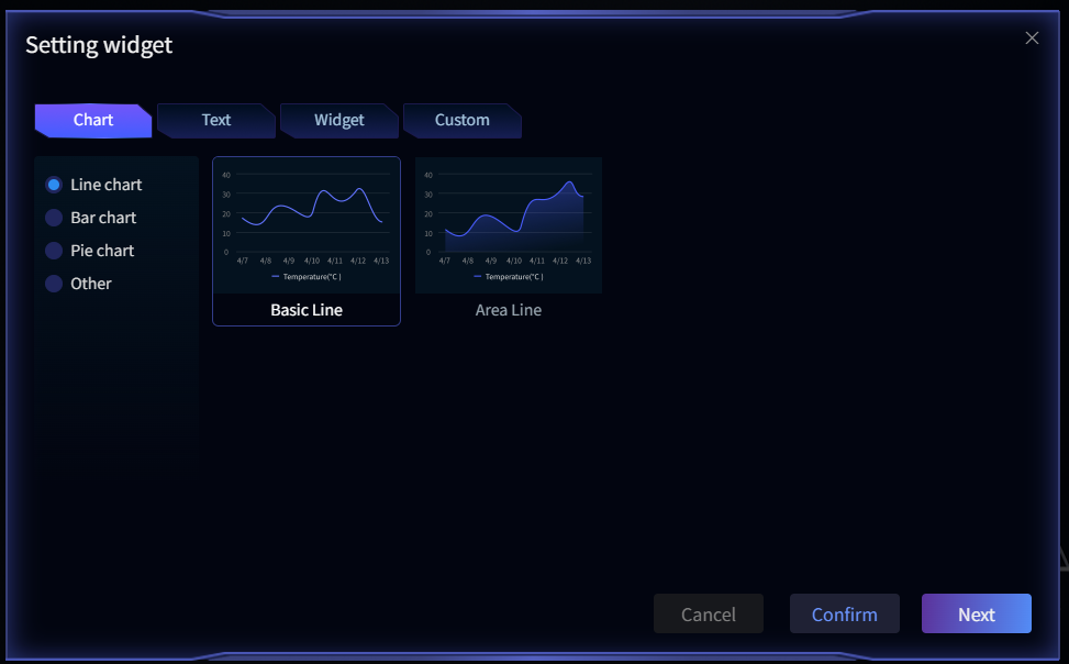
1. Select Data Source, 2. Select Device, 3. Select Device Data Point, 4. Select Time Range
Model Layers
Within a single scene, multiple Model Keys can be configured (usually split based on system dimensions). Each Model Key must be associated with an independent model layer, enabling separate model display by system or layer during scene rendering.
tips: If your required layer category doesn't appear, refer to prerequisite-configuration above to add it.
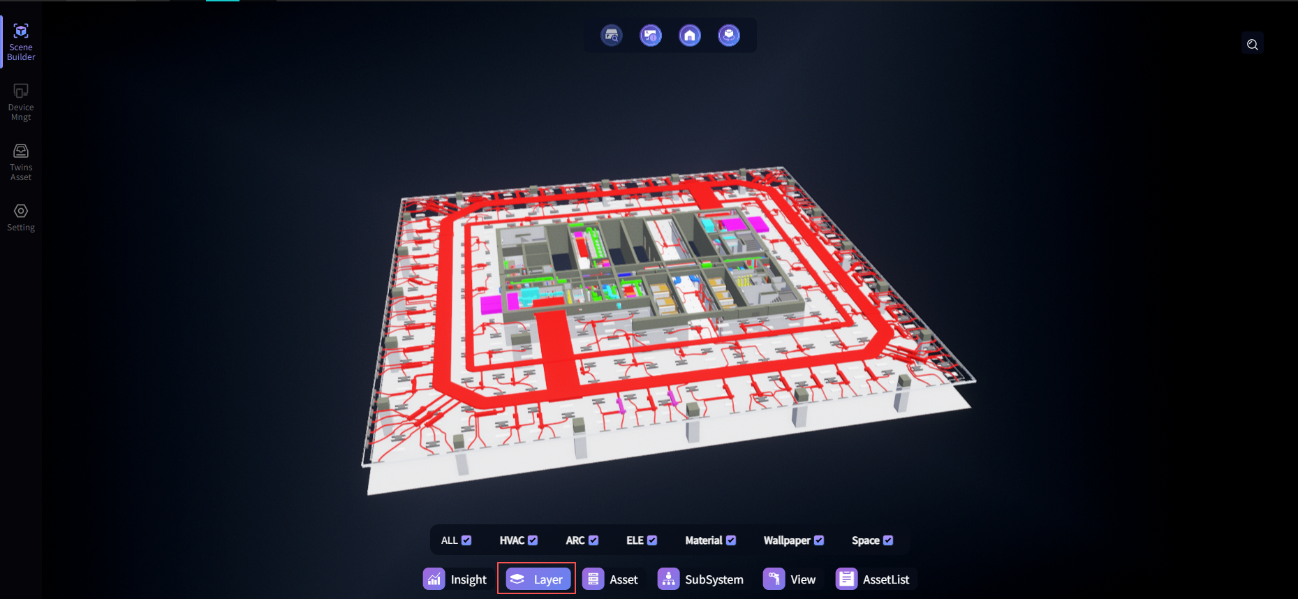
Twins Asset List (Asset List)
Once configured, the list will appear in the left/right drawers.
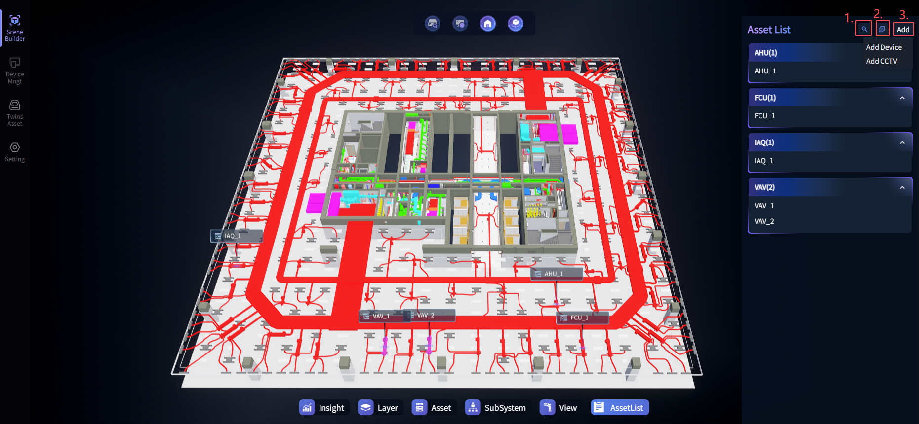
To associate asset devices or real-time data with 3D models, point configuration is required at the corresponding model locations. After configuration, all mapping relationships are uniformly displayed in the Twins Asset List. 【Add Twins Asset Operation Guide】
The list supports grouping and displaying asset devices by type. If a device is connected to real-time data, its status can be viewed directly in the list. Clicking any device item automatically focuses and locates the corresponding model in the scene, allowing querying of the device's real-time data, basic information, maintenance status, BIM information, and other details.
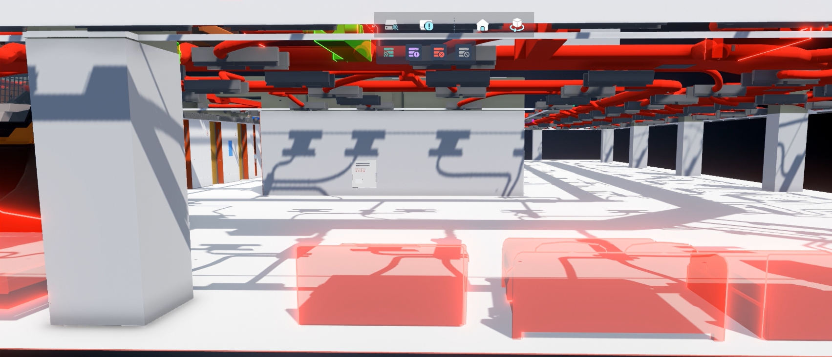
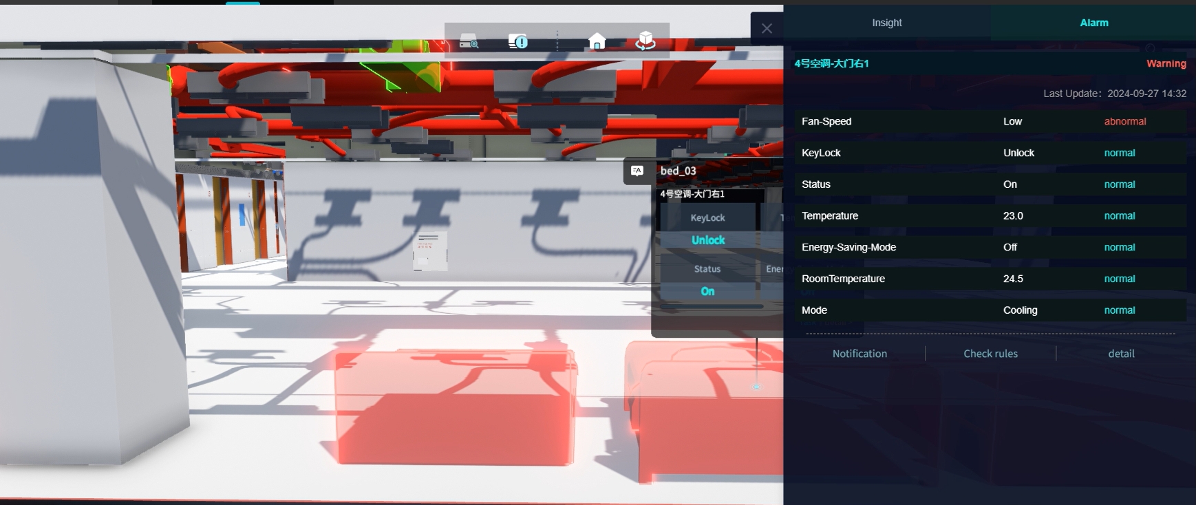
Real-time Data Display: When a device is in a warning state, the model color will change; click the model to view the warning reason and detailed information.
Asset Hotkey
Once configured, it will appear as a quick button in the bottom Hotkey list.
After enabling the Asset hotkey in Hotkeys, you can view the basic information, real-time status, and model information of configured Twins Assets by category. Configuration via 【Add Twins Asset】 must be completed before use.

Quick View
After configuration, frequently used views can be saved in a list for one-click quick switching.
Click Add to create a new view. After adding a view, click on any view to quickly switch between different perspectives.